
In my initial approach to designing a replica Spitfire throttle quadrant for use in flight sims, I chose to use rotary potentiometers because I initially thought that I would be able to place them back to back inside the lever axis shaft, with one for the throttle and the other for the airscrew control. This proved difficult to realise and I opted to place the two potentiometers outside the axis.
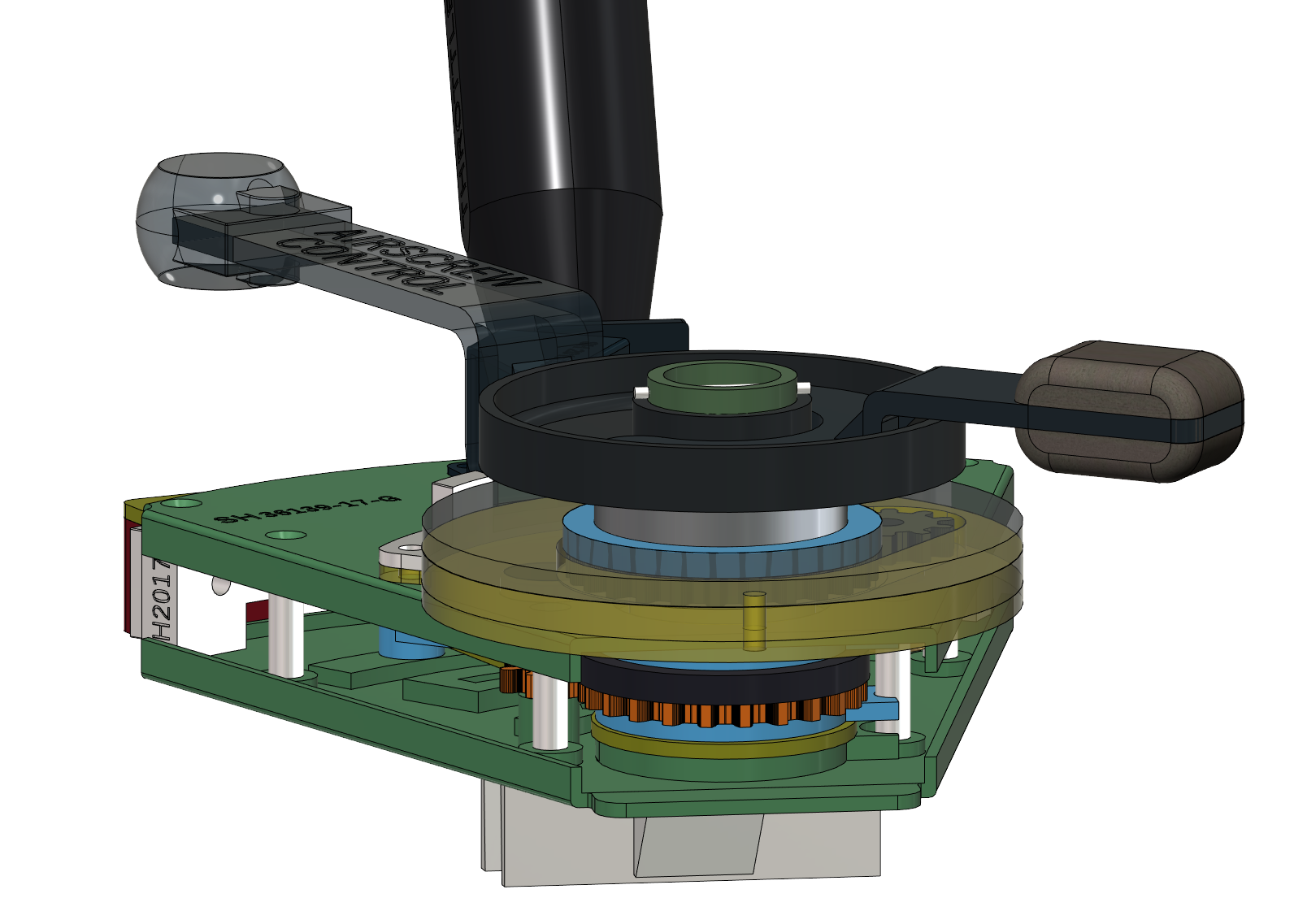
Original replica Spitfire throttle quadrant design showing the gearing for throttle and airscrew levers and their associated rotary potentiometers.
There was just enough room for them to be fixed to the front plate and to have them meshing with the two levers via gear cogs. I was happy with this option as I was able to hide the two potentiometers inside the quadrant without altering it’s precise exterior dimensions. I was also able to design the gearing so that the limited lever movements (throttle 43° and airscrew 55°) could be amplified to get nearer the full potentiometer operating range, in my case 240°. Due the constraints of space I only managed to get 141° on the throttle potentiometer and 138° on the airscrew pot. This was well within the working range and allowed the possibility to set the gearing either side of true centre if needed to use a different segment of the potentiometer working range. While this system works perfectly well, it is a bit fiddly to set up, so I had always imagined that someday I would place the two potentiometers outside of the throttle quadrant.
In the real Spitfire the throttle is activated by a rod attached to the lower part of the lever which protrudes from the bottom of the quadrant which runs forward to the engine compartment, and the airscrew mechanism is controlled by a “Teleflex” Bowden cable which also runs forward to the airscrew blade control unit. So my idea was to design a box holding two slider type potentiometers and to place this forward of the throttle quadrant, with each slider linked to the throttle and airscrew levers by rods or gained cable.
For the throttle lever this was quite simple as all I had to do was to design the lower part of the lever that protrudes below the quadrant. I was able to do this by inserting this new “extension” part into the existing throttle lever in place of the original gear mechanism. The only issue being is that due to the original length of the lever, the extension arc moves about 3” and the sliders that I found have an operating length of less then 2,5”, so I had to reduce the length of the lower part of the lever to obtain the required travel distance.
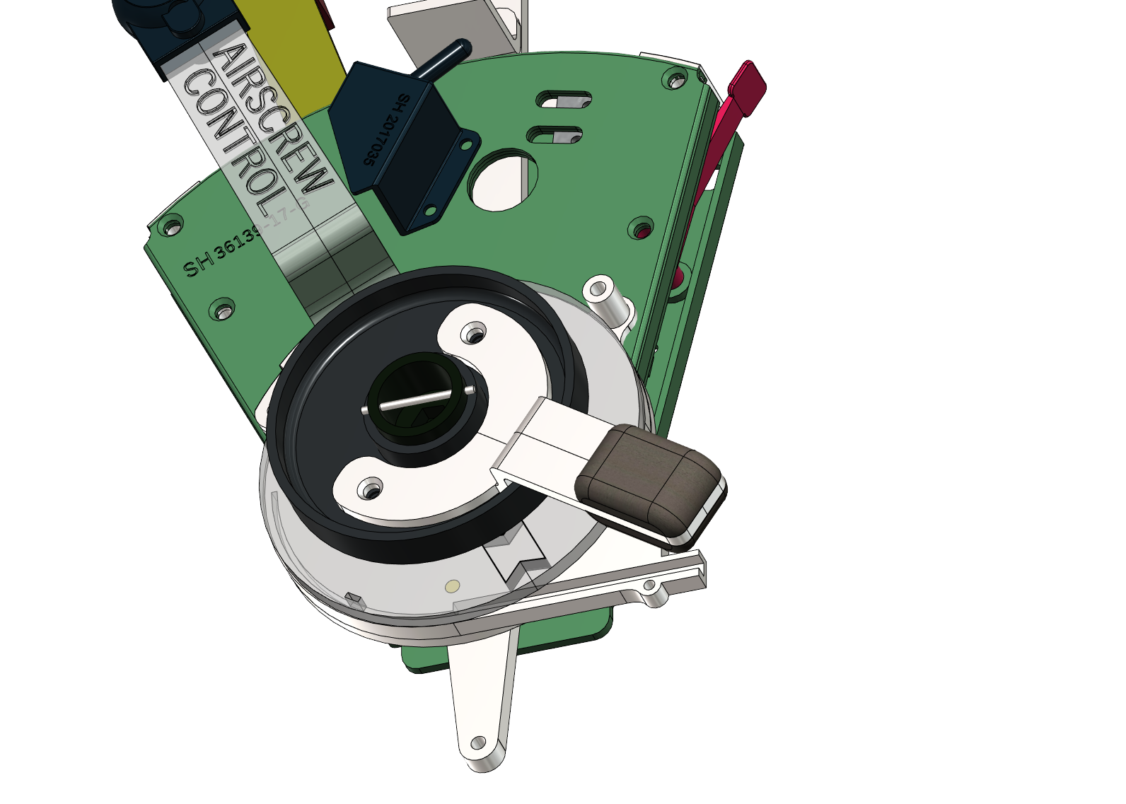
The re-designed replica Spitfire throttle quadrant showing the throttle lever “extension” arm protruding from the lower part of the unit and the design of the track in the airscrew lever baseplate for the flexible and rigid parts of the airscrew actuating rod. The WEP lever is shown top right.
For the airscrew control lever I needed to convert its rotation into a linear movement and I toyed with the idea of using a real Bowden cable (like the ones used on bicycles for the brakes). However I realised that this would be messy to cut to size, problematic to attach the free end to the slider, and be totally overkill in terms of strength for simply pushing and pulling a slider, so I opted for a more simple solution.
When PLA is thin it is quite flexible, so I came up with the idea of using this property for part of the actuating rod in the area where it would need to bend and to include a fatter rigid section for the area where stiffness was required. This was because I wanted to limit any play in the linkage. So I designed a track in the aircrew lever baseplate in which the rod would slide. It has a small tab at the lever end that slots into the base of the lever. Upon testing I was surprised at how well this set up works requiring only a little sanding and filing to ensure smooth tracking. Regarding length, here the issue was that the 55° rotation of the lever only gave just over 2” of linear movement to the actuating rod, so I decided to go with it and not use the full working distance of the slider.
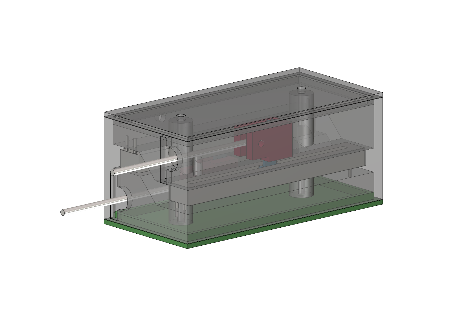
Having sorted out the quadrant side of things I was able to work out the position and distance of each actuating rod to the other which led me to design a small box in which to fit the two sliders. The articulated rod linkages that snap on to the slider levers ensure minimum play and allow for the small angle change of the throttle lever actuating rod over its arc of travel.
For ease of access to this prototype set up I decided to fit this “actuator box” to the rear of frame 8 in my Spitpit and this is where it will be probably installed in the cockpit panel modules which I make for customers. In time, if there are no issues with reliability, I will no doubt print up longer actuating rods and in my simpit install the box out of sight somewhere between F7 and F8.
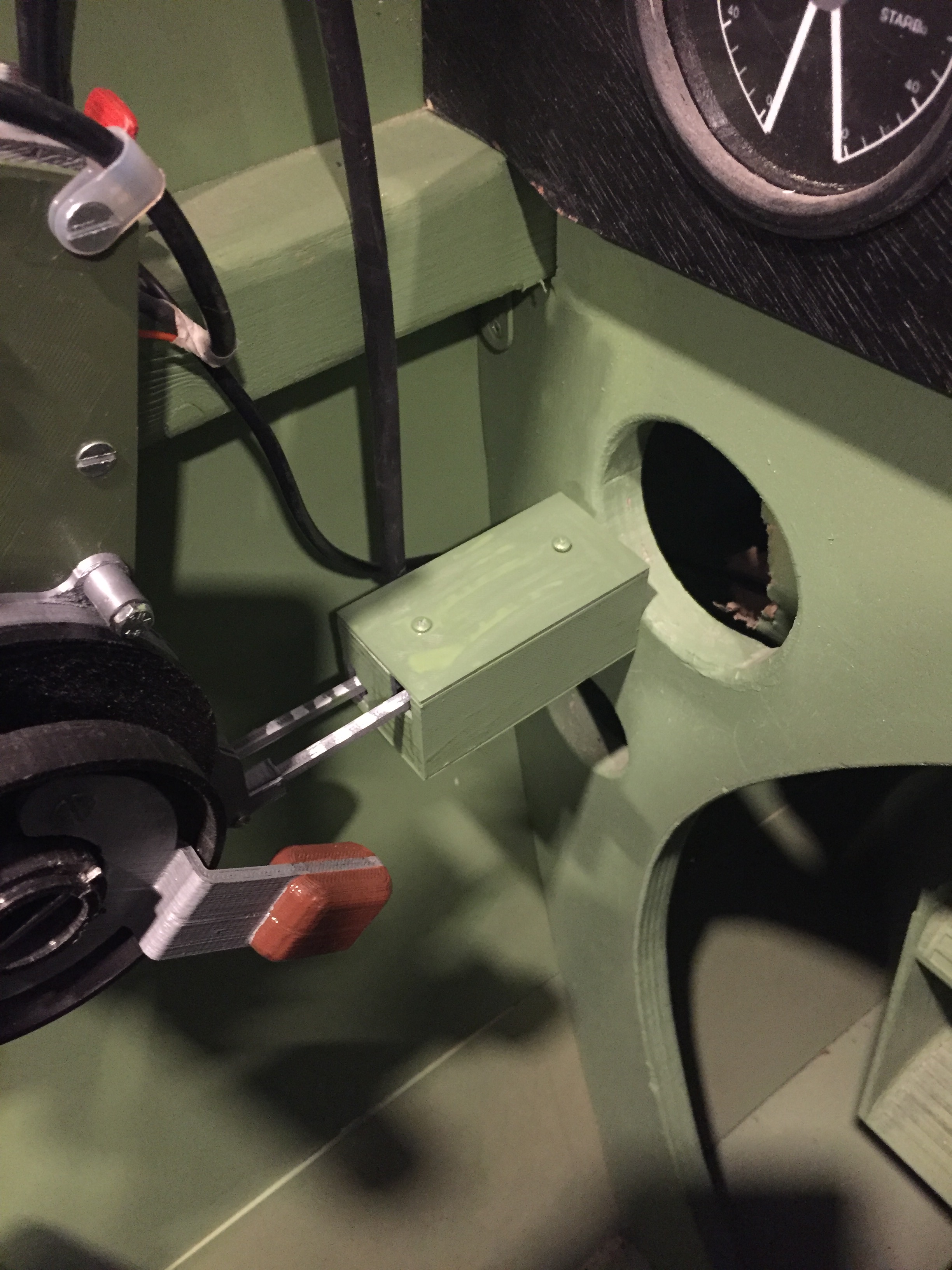
The “actuator box” fixed to the rear of frame 8 in the authors Spitfire simpit.
The re-design review of my Spitfire IX replica throttle quadrant would not be complete without mentioning the modifications to the WEP actuating mechanism. While most people know that there was no WEP switch available on the Spitfire IX, earlier Spitfire variants did have this function and my early throttle quadrant design had this function discretely integrated hidden inside, a switch being activated by an arm on the throttle lever when it was pushed beyond the max take off stop.
While this system also functions OK, it does create an issue when calibrating the throttle lever in the Windows game controller panel, as when you move the throttle to its fore and aft limits the WEP arm activates a switch just before the lever is fully forward, and this activation tells the system that the calibration is OK when in fact it should be one or two degrees further forward.
To get round this issue I dissociated the WEP arm from the throttle lever and integrated it to the top right plate spacer with a little lever with a red tab that just appears at the front of the quadrant gate. While this is a departure from the visual reality of the Spitfire IX set up, it does allow for full throttle calibration and for the WEP function to be activated when flying earlier Spitfire variants in simulators.
I have had occasion to make up a replica Spitfire I throttle quadrant with the red boost cut-out lever added to the unit, so this version could be made available for customers who want to fly early Spitfire variants.