
In between flying online and other activities I get a bit of time to undertake my favourite pastime which is doing R&D on my replica Spitfire sim controls. It’s the occasion to imagine how to design mechanical operating functions that also include modern electronics to transmit instructions to the flight simulator, instead of the original pneumatic, hydraulic and electric systems.
I recently had the opportunity to review my original design of the Spitfire spade grip following a visit to the Kent Spitfire & Hurricane museum at Manston, where I donated a replica Spitfire control column unit for a replica cockpit section that they are restoring.
As you will see from the heading photo I noticed that my spade grip seemed a bit thinner in section than the real one in their MkXVI, so I decided to re-design it with a slightly thicker section, which was easy enough to do and to have a go at finding a way of making the safety catch indicator pin pop in and out of the top of the firing button casing. Up to now I had only left a hole in the casing for the pin and had not got round to adding this rather nice visual and tactile detail.
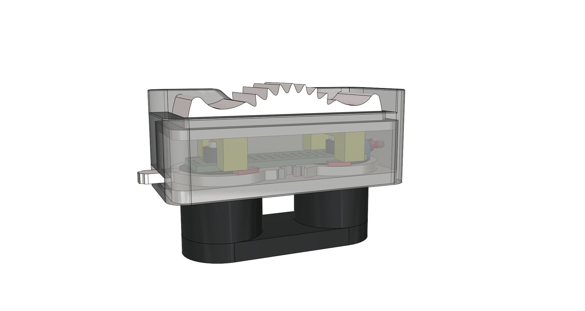
The Spitfire firing button I designed is a replica of the later pressure plate type and I replaced the original pneumatic valves with two micro buttons under the spring loaded plate that allow one the other or both buttons to be depressed, thus mimicking the operation of the original unit. My initial design also includes a mechanical safety switch locking mechanism which blocks plate movement when in the ON position.
The locking system works using two gear linked rings, each having two cams on their upper surface which engage under four legs fitted to the underside of the pressure plate. Above the two rings a small piece of circuit board is added to fit the two micro pushbuttons and this board also secures the two rings in place. The lower ring has a small lever that protrudes through a slot in the base of the firing button housing that is operated by thumb and the upper ring has a paddle that extends downwards through a slot in the base plate where an electro-optical switch is located. This tells the sim when the catch is operated.
The current system works fine both mechanically and electronically, so I hoped that I would not have to change its original design.
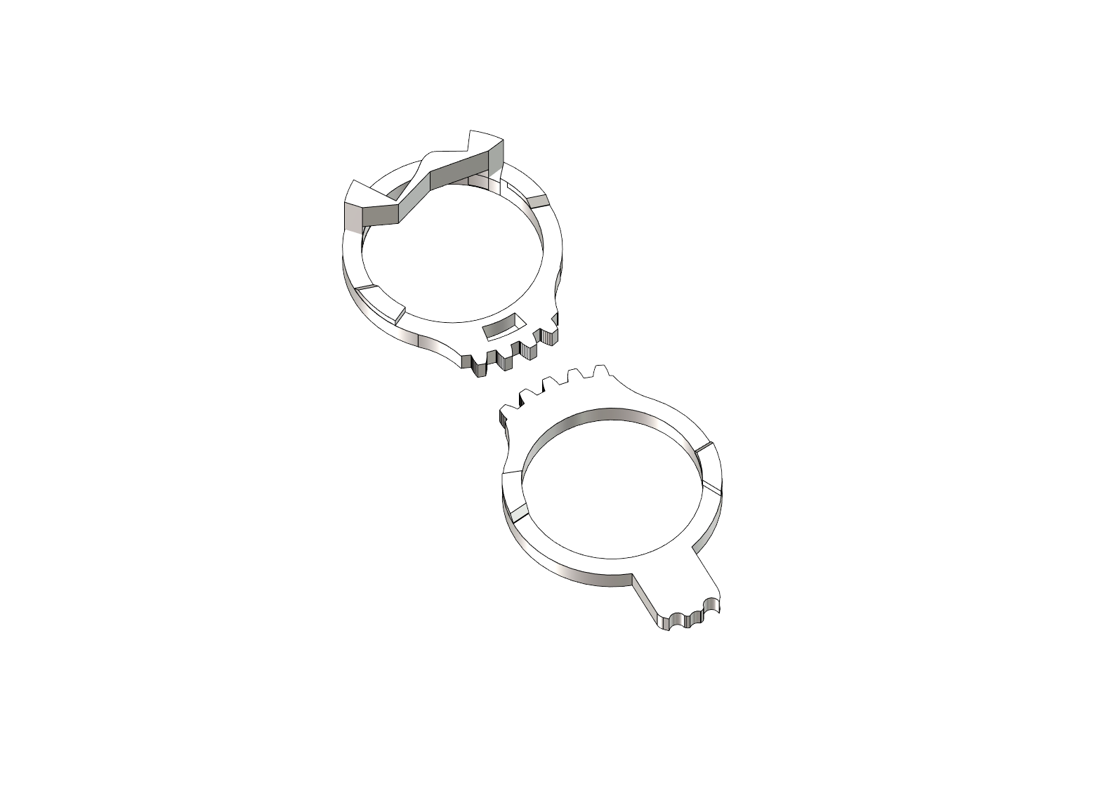
The challenge was to add a further cam to the upper ring in the limited space that would operate a spring loaded indicator pin. After some thought and a bit of trial and error I came up with the idea of a short aluminium tube added to the inside of the firing button housing, in which a spring loaded pin is installed. The rear of the pin extends outside of the tube when the safety is off. A thin cam was then added to the top side of the upper ring to activate the pin.
The difficulty was to get the dimensions right so that this new cam would not foul the movement of the pressure plate or its two upper support legs. Luckily I have two 3D printers one that prints quite fast for the larger more bulky items and a newer more precise machine that is good for printing small fiddly units.
A further consideration was assembly, as the pressure plate and its casing snap on to the base plate which is integral with the spade grip to which the two geared rings and circuit board are fitted. With the pressure plate inside the casing, one first has to slide the lower ring lever through the slot in the casing with the lever in the middle position, then before pushing the top of the casing down, slide the locking lever to the right to facilitate the passage of the indicator pin cam. This is delicate as the pin is free floating in its tube and the trick is to hold the pin in its outer position from the outside of the casing with some self locking pliers.
Once assembled the SH pressure plate firing system is robust so the assembly technique is only useful to me as I need to assemble and disassemble a few times to check fitting and functioning before adding a spot of superglue to cement the casing to the baseplate.
Now that this job has finally been attended to, its time to pursue the next piece of equipment which is the AM type 5C/543 switch. I have been able to procure a real switch and when comparing its dimensions to the model I had created using dimensions gleaned from Supermarine drawings, I noted some small discrepancies which need to be corrected. So its another occasion to re-design my prototype where I hope to also improve the reliability and feel of the switch lever. But more of that in a further article