
I am a bit late in publishing this follow on as I got tied up building 3D cockpit parts for customers and that took priority over writing articles. Recently I looked at the the number of views on the subject and had some enquiries for further details. These were indications that I should not wait any longer to publish the part 2 that I had promised.
Drafting the plans full size
As mentioned before you need to start from the original engineering drawings that have legible dimensions on them. These dimensions are in inches, so to avoid mistakes use imperial rulers to transcribe the dimensions full scale. I started by using 4mm thick plywood panels of sufficient dimensions so that I could draft frame templates on them (ie the panels need to be at least 45 cm wide for a half frame cut vertically). Once cut out in this thinner plywood, the templates were then used to draw the frame details onto the thicker (18mm) plywood that I used for the frames and other cockpit parts. This method allows some optimisation of the 18mm panels as you can use several templates on one panel.
Before tracing the frame coordinates on the 4mm template panels, you should first take great care to trace the centerline and the other four vertical lines which are called B1, B2 and B2,5 at 5”, 10” & 13” either side of centerline. Horizontally the so called ‘waterlines’ are spaced 4” apart with WL0 set at the datum longeron height with WL 1 to WL 7 above and WL -1 to WL -7 below.
To ensure that all these lines are properly perpendicular and parallel, I made myself a long set-square which ran in a track along the edge of the drafting table.
Once you have your ‘grid’ set up you can start to plot the outer and inner frame dimensions on it. It has been said that there is never a straight line on a Spitfire and this is particularly true when tracing the frames. The drawings often give indications of arcs to draw as many of the inner frame profiles are made up of adjoining arcs of different radii. The centre points of these arcs are sometimes difficult to establish from the available drawings, so take your time to carefully locate and plot them on your template.
It is important to realise that some of the drawings are for only the left, right, front or back of a particular frame and that sometimes these are not symmetrical left and right in terms of cut-outs for instruments or cable runs and for lightening holes. As mentioned before, the back of frames is slightly smaller than the front due to the tapering of the fuselage as you move aft. Remember also to take into account the thickness of the skin you will be using. In the cockpit area the aluminium skin of the real Spitfire was just under 1mm thick, so if you are going to use 4mm plywood you will need to reduce the exterior frame dimensions by 3mm so that the outer skin is true to scale.
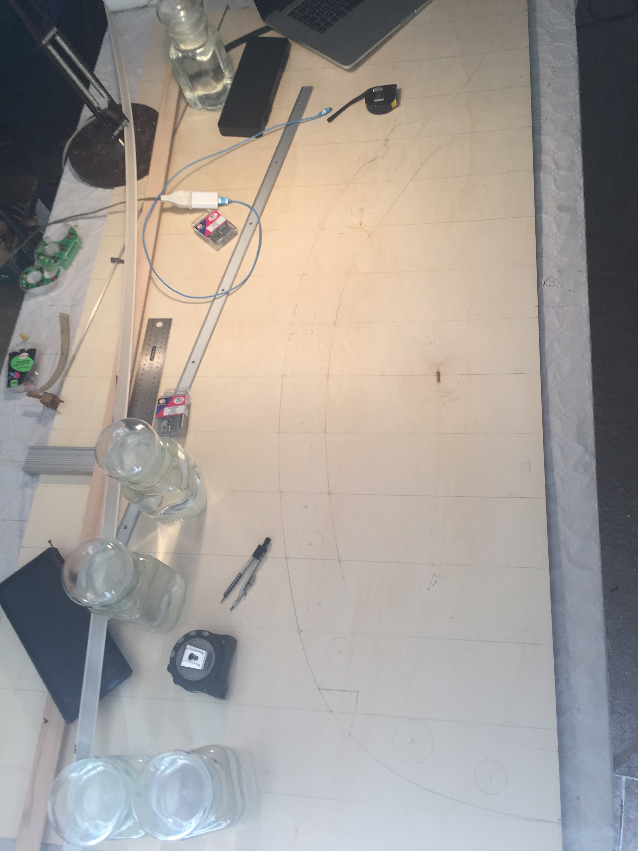
Once you have plotted all the available dimensions on your grid it will be time to ‘join the dots’. Getting this right with appropriate smooth curves is quite a challenge. 1 or 2 mm out on a particular point can mean that is is nigh on impossible to join the adjoining points on a smooth curve, so you need to check your measurements and plotted points again and again to get it right. To trace the curve profiles I used thin wooden battens and rather than just using nails to hold them in place I added weights using water-filled glass jars.
The 4mm plywood is easily cut with a jigsaw. For accuracy I cut just outside the traced lines and then spent time sanding and filing down to the profile. Using the templates you can trace the frame profiles on thicker plywood panels. Because the trace line is outside the template you need to center the jigsaw blade on the traced line to obtain the true profile dimensions.
Aligning the frames
Once you have all the frames cut out (7, 8, instrument board, 9, 10 and 11), you now need to think about how to fit them so that they align on a common reference point and that they are correctly spaced. Frame spacing is not standard on the Spitfire so you need to note the varying measurements and to plot the frame center-lines on a datum. I used 2 longitudinal reference points, one being the designers fuselage datum longeron which is at about half cockpit height and an artificial ‘floor’ which was at a set height below datum. With both reference points I was able to space the frames correctly apart as they are all perpendicular to the datum line (except for the last fuselage frame where the tail section joins – but we don’t go that far aft in this cockpit).
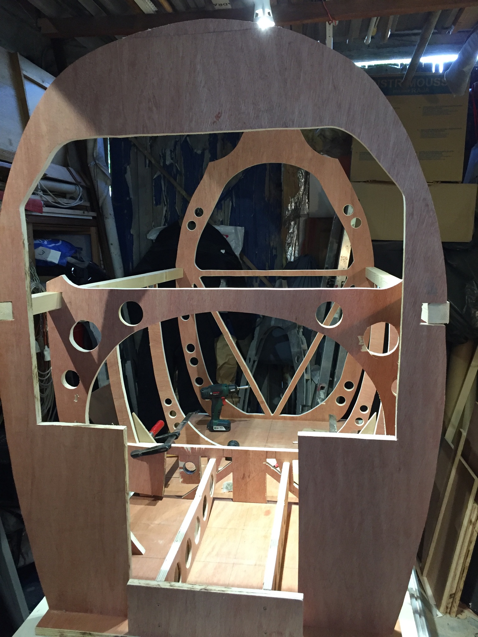
In the photo opposite, the cockpit build seen from the front starting with frame 7, with cut-outs for the rudder pedal units and for the pc which will be on a shelf above the pilot’s feet. Frame 8 is only the lower half, as the instrument panel will come and finish off the upper cockpit profile. Frames 9 and 10 are also half frames.
In the absence of a jig, note the false floor which allowed me to have a second horizontal reference on which to site the frames and the wooden bars each side which represent the designer’s fuselage datum longeron. The fuselage datum bars have not yet been secured and you can see that some bending will be required to get them to fit, this being due to fuselage taper not being a straight line.
I chose to place the false floor lower than the traverse at frame 9 in order to better simulate a floor-less cockpit, as the pilot’s feet only rest on the traverse when they are not on the rudder pedals. The traverse at F9 is also required for fitting the auxiliary fuel tank cock and jettison lever. The other advantage of a false cockpit floor is that I didn’t have to build a dolly to fit the lower fuselage profile – I simply put locking castor wheels under the flat base which allows me to move the cockpit around at will.
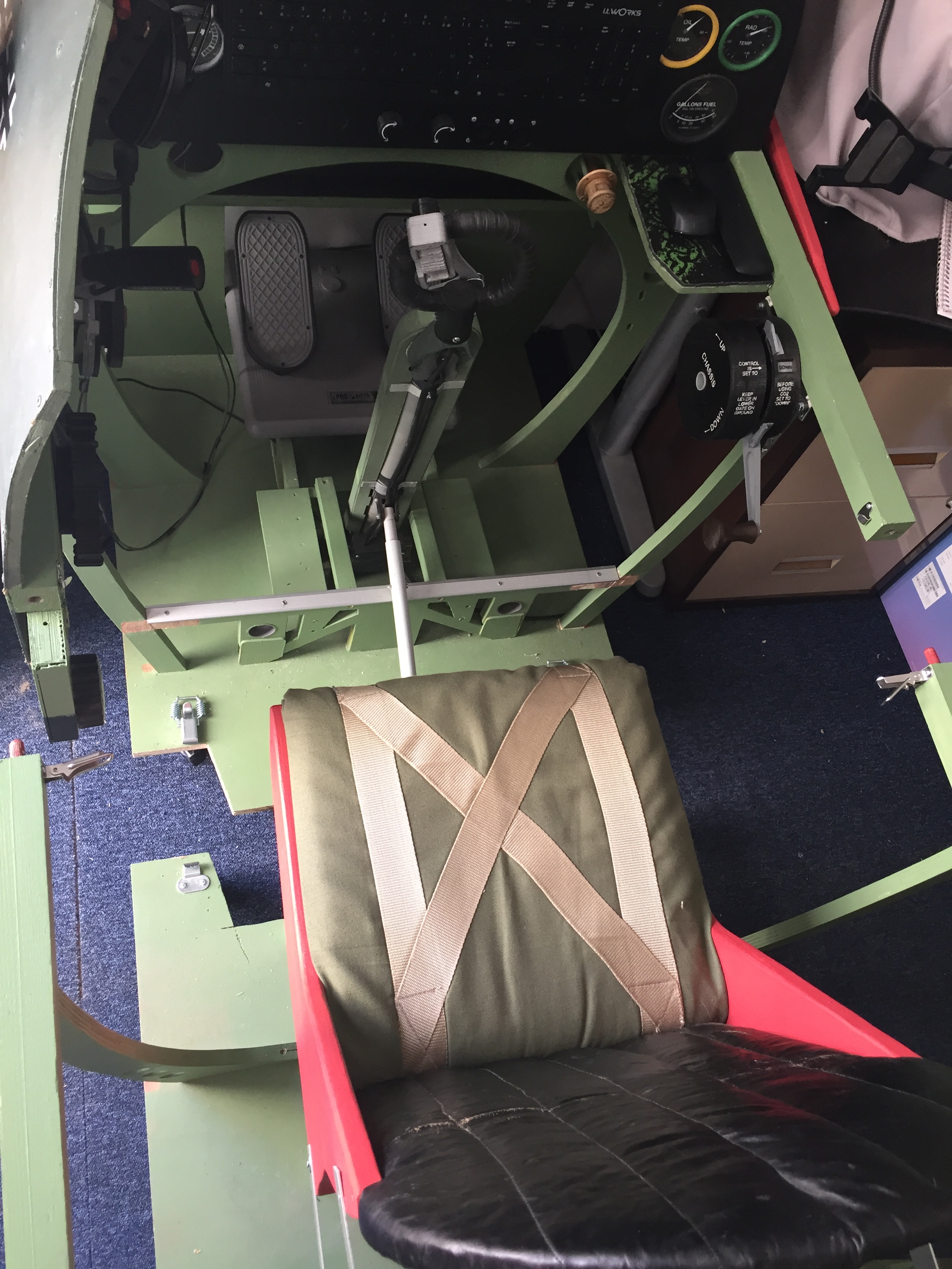
The next headache to overcome is that the Spitfire fuselage section in the cockpit area is 85 cm wide and standard doors are only 80 cm wide. Because I planned to take my cockpit to exhibitions and airshows I chose to cut it into lengthwise sections that would fit through a standard door frame. I was lucky that the distance between frame 7 and frame 11 is less than 160 cm, so I was able to cut the cockpit in half between frames 9 and 10. The other advantage of cutting the frame in two lengthwise is that you can make the rear part with the pilot’s seat roll backwards for ease of access. This avoids having to climb into the cockpit via the rather small pilot’s access door. Once seated it is a simple affair to roll forward and clip the two sections together. The photo on the left shows how I cut the false floor to allow the protruding pilot’s seat to have castor wheels located forward to stop it tipping.
Talking about the pilot’s seat, in the real Spitfire is it suspended on an adjustable frame that is fixed to the traverse and lugs on frame 11. This frame is a little complicated to reproduce and I was concerned about the strength of my wooden frame not being able to support the weight of the seat and pilot. So because the seat has no real impact on how you fly I chose a fixed height and supported it with legs onto my false floor. One day I plan to beef up frame 11 and make up the adjustable seat frame, but this will just be to keep me occupied once the other more important items have been developed and integrated into the cockpit.
Before closing this section I strongly recommend to paint the frames before assembly and to not fit the skin panels until all the controls, instruments, wiring etc have been installed and tested. As you will find out the Spitfire cockpit is small and cramped – in the real aircraft the seat was easily removed to allow fitters and technicians a bit more space to access the controls and instruments – but even so space is very constrained and larger individuals will have a lot of trouble tightening small nuts or trying to retrieve a bolt, screw or washer that has slipped out of one’s grasp. You have been warned !
Integrating the simulator controls into the cockpit
I started by taking every care to get the control units correctly positioned in relation to the instrument panel and the datum longeron. This was fairly easy for me as I already had the control column on a base and the left hand cockpit controls on a small piece of cockpit panel. I had to adapt the throttle quadrant support to fit the new 40x40mm fuselage longeron and this was quickly 3D printed. I also had to modify the support box for the elevator and rudder trim wheels so that they would sit at the correct height below the fuselage datum.
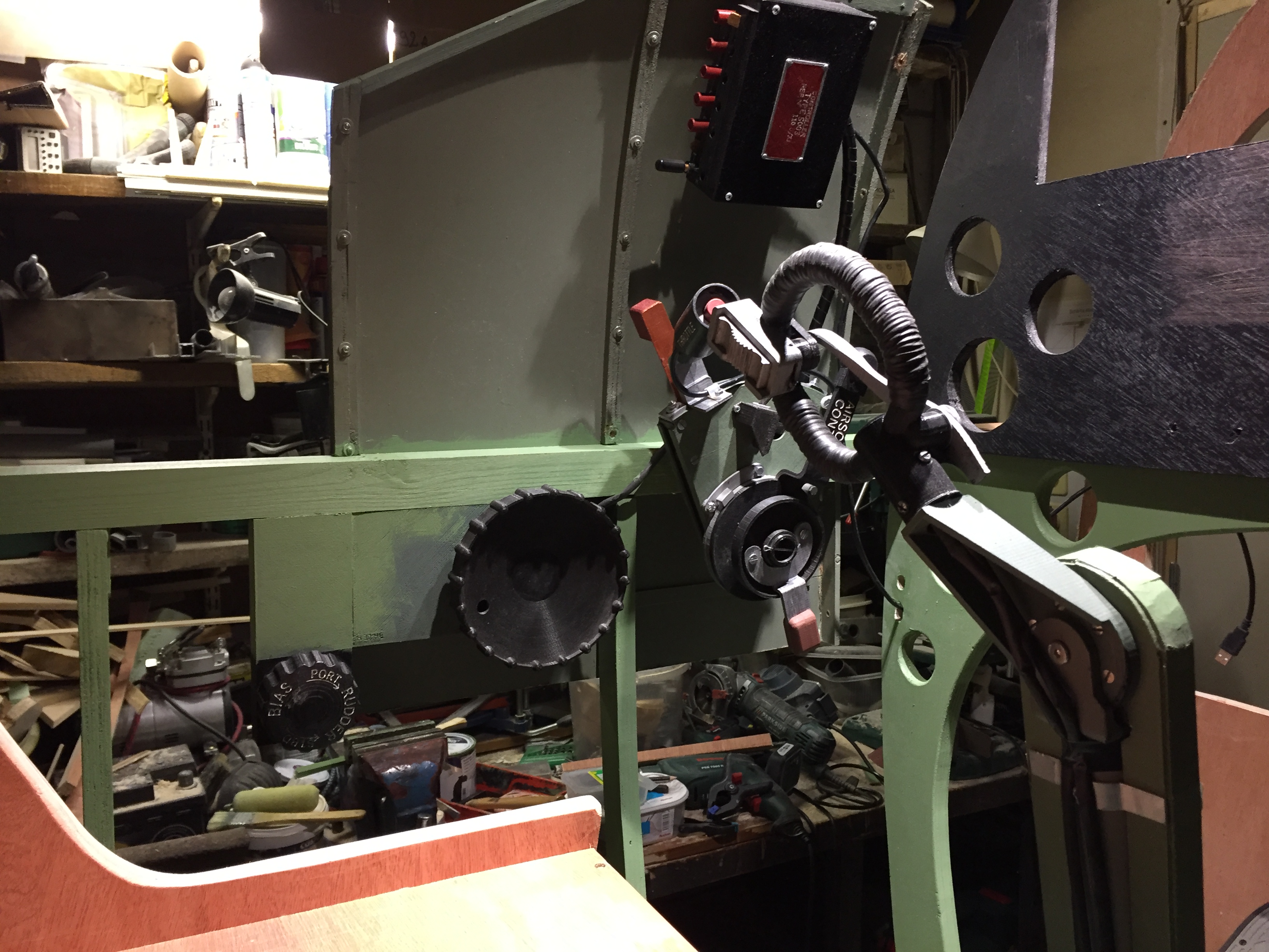
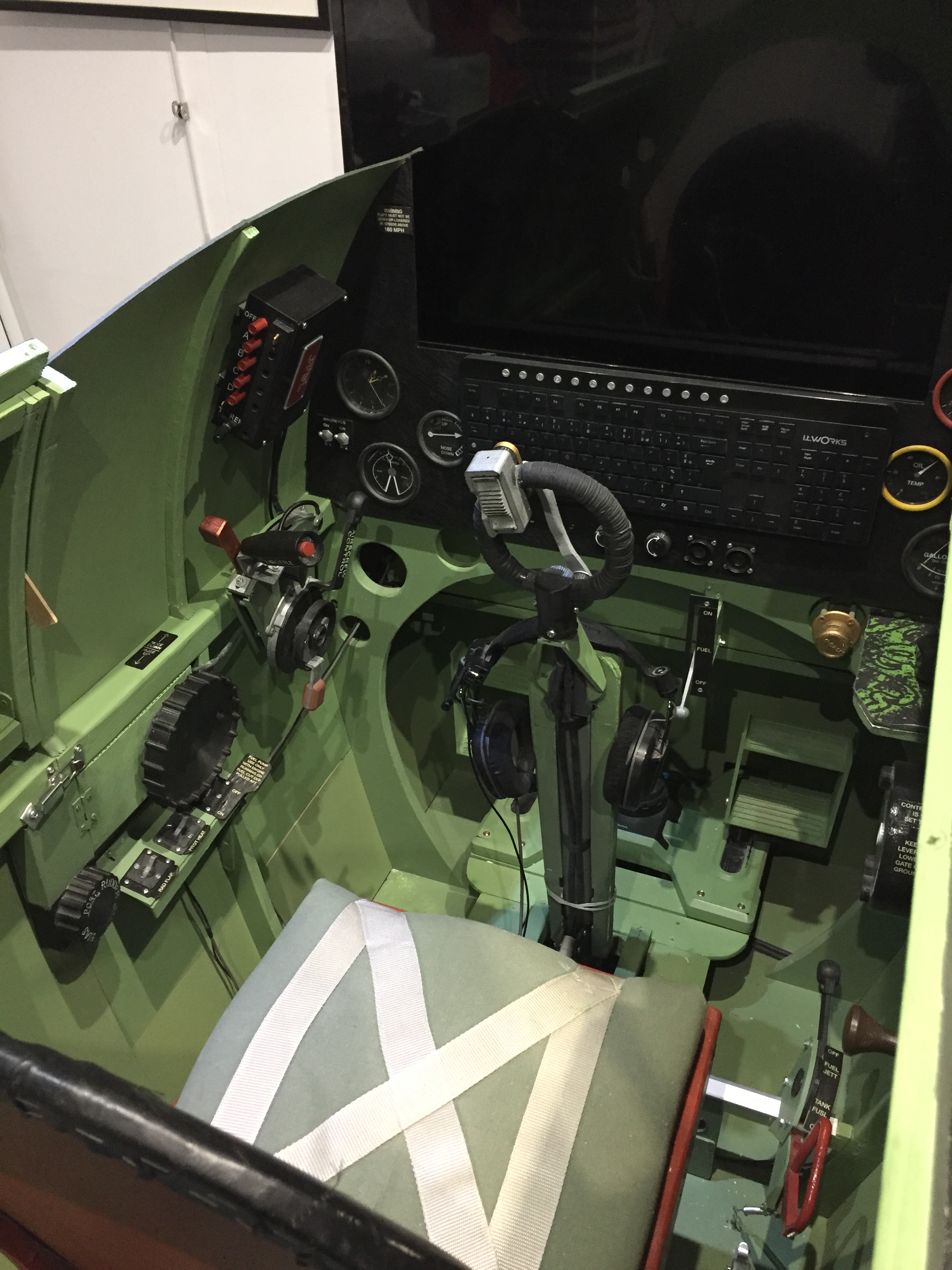
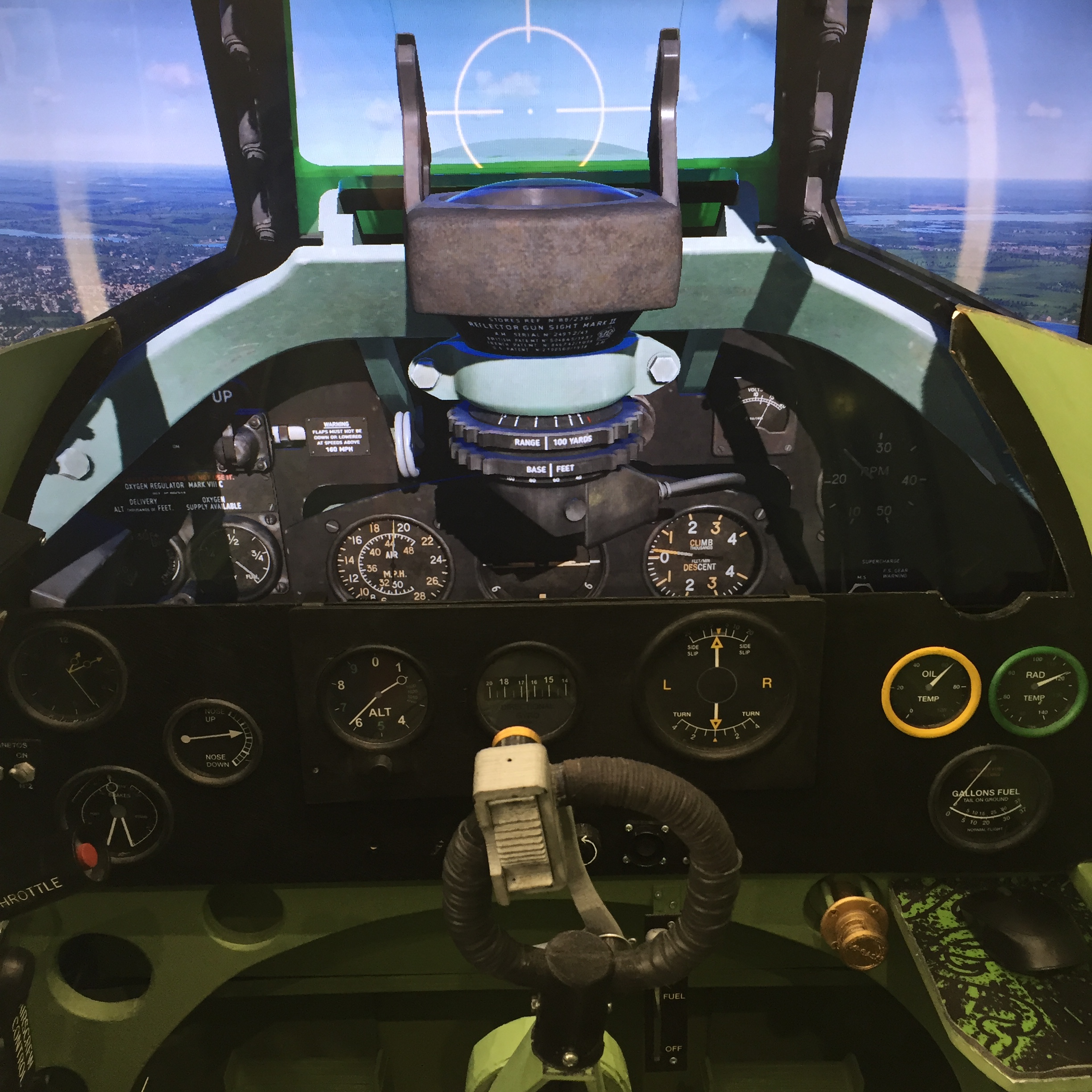
The fore and aft positioning was fairly easy to check as once the control column is correctly sited in relation to the instrument panel, the throttle lever in it’s aft position should be level with the spade grip with the control column in its rest position. See photo opposite. On the other side of the cockpit the chassis unit axis is just forward of frame 9 and the top of the unit is level with the fuselage longeron. Of note is that I had to hinge the rudder trim box so that it could fold inwards as my 80 cm cockpit section cut line was just at the forward part of the cockpit access door. It also took me some time to get the correct height and position of the rudder pedals. I haven’t yet got round to making a replica rudder unit, just scale Spitfire footrests for the CH Pro rudder pedal unit. So it took some care and attention to get the proper footrest height and fore and aft position for my particular seat height and leg length. Remember in the real Spitfire the seat is adjustable in height and the rudder pedals can be adjusted fore and aft using the knurled rings on the rudder bars. This allowed both short and lanky pilots to fly the Spitfire, which wasn’t the case for the Bf109 who’s seat height was not adjustable.
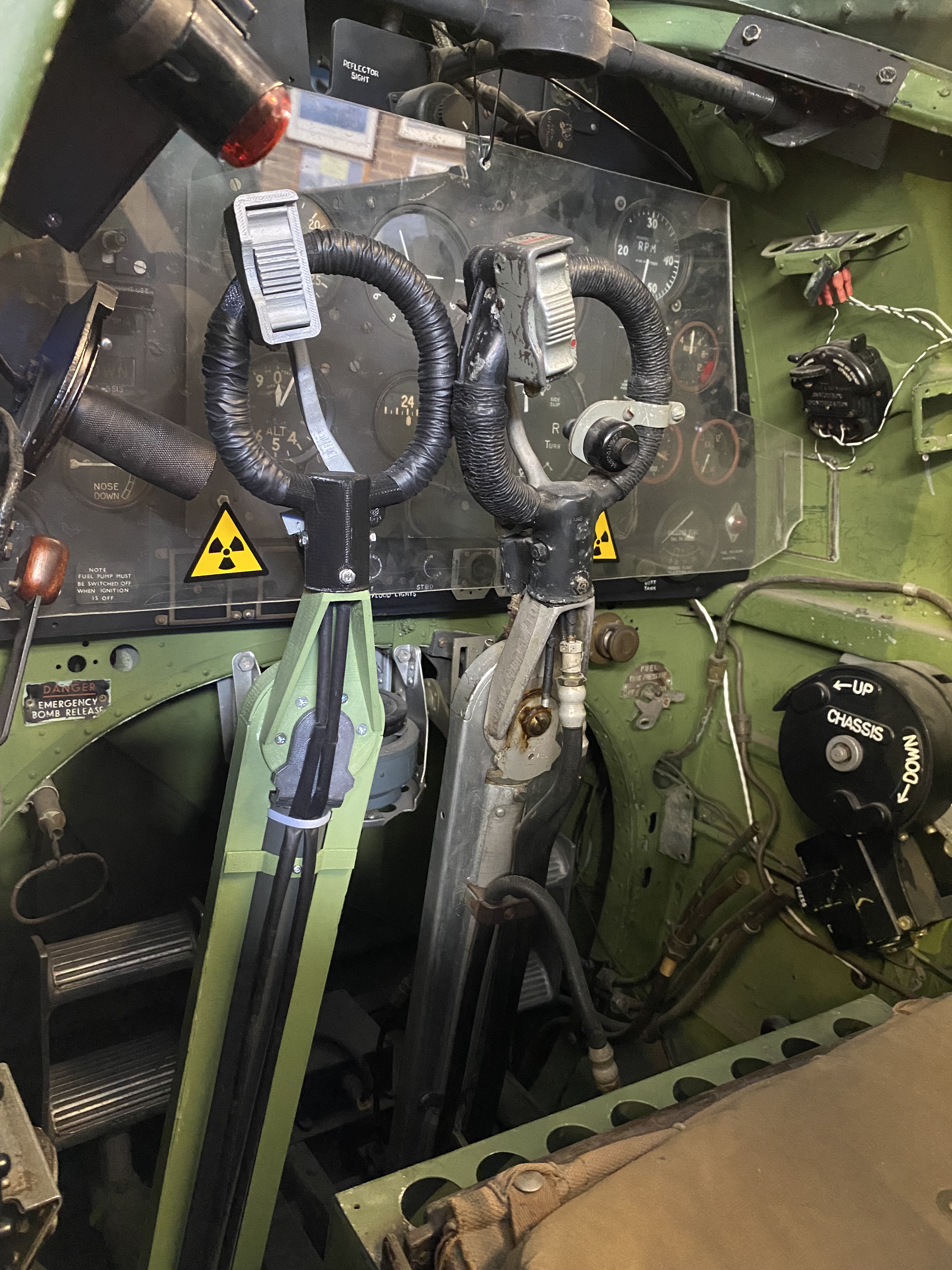
I had a lot of trouble finding drawings that give the total height of the control column from its lower fore and aft rotation axis to the top of the spade grip. One can find drawings which give the height of the column to the top of the chain guard, but you need to add the gooseneck fitting which rotates left and right and the height of the spade grip handle – these are less easy to find. However I am happy with the result of my column, as I offered one to the Spitfire & Hurricane Museum at Manston and they let me place my replica column alongside the original in their Spitfire XVI cockpit. As you can see from the photo the match seems pretty good.
So which functional sim controls did I finally manage to integrate into the cockpit ? In addition to the basic control units already mentioned, I added the starter and booster type 5C/898 buttons situated on the lower part of the instrument panel. These were modeled from a real button and I was able to reproduce the spring stiffness of the original. For the moment I have not yet made the spring loaded button covers as I still need to figure out how to link these to a toggle function so that they activate the covers in sims like DCS. On frame 8 just below the instrument panel I added the main fuel cock – on the Spitfire IX this only has a single lever. On the traverse of frame 9 to the right of the pilot’s seat I fitted the auxiliary tank and jettison handle unit. Finally, below the trim wheels I added the three 5C/543 switches for the fuel pump, pitot heat and the radiator auto/manual mode selection. I initially designed these switches with rough measurements taken from some engineering drawings where the exact dimensions were not indicated. Later I was able to purchase a real switch and discovered that I need to adjust my initial designs for them to be accurate replicas. Although I have made several sets of flaps operating levers for customers I have not integrated this item into my ‘track IR’ style cockpit, as if I position it correctly on the top left of the instrument panel, it would blank out an important area of the video screen. So for the time being I assign the flaps toggle function to one of the buttons on the VHF radio RCU.
Adding to the look & feel
With these basic sim controls fitted to the cockpit I knew it was going to be a bit bare, so from the start I had planned to add what some call ‘eye candy’. These extra items include dummy gauge facings for the lower sections of the instrument panel and of the blind flying panel, dummy cockpit lighting dimmer buttons, dummy magneto switches and a Ki-Gass fuel primer pump which has yet to have it’s electronics fitted. I plan to add some more functional units ; the wobble pump and the identification lights morse unit on the right hand cockpit panel, the supercharger switch, the fuel pressure selector lever, the fuel contents button, the altimeter set knob, working magneto switches and the flaps operating unit to the instrument panel, plus the compass with working bezel ring and the gyro gunsight with working range and e/a span bezel rings – but these latter units will have to wait until I make the move to VR where I will be able to remove the video screen.
Several people have commented on the fact that in VR you only see what’s in the goggles so why bother with all the eye-candy. Well, there’s a simple answer to that ; before putting on the goggles I would rather like to see that I am climbing into a realistic looking cockpit rather than getting into a sort of unidentifiable framework that supports all the controls.
Still work to do
So while the current cockpit controls are largely sufficient for those who try out the simulator at meetings and exhibitions, for my personal pleasure I would like to include as many other controls, switches and buttons such that the cockpit would be fully flyable in VR without the use of a mouse or keyboard. In the DCS Spitfire IX I have identified about 80 useful clickable controls. The main challenge of moving to VR is that it means adding a full instrument panel, the gunsight , windshield and sliding hood plus getting the mechanical hood release and jettison functions to activate in the sim. So enough to keep me busy for some time yet.
In conclusion the build project was not particularly complicated nor long to undertake per se. What did take time was finding the relevant engineering drawings, trying to interpret or infer measurements that were often illegible or missing and on deciding about how much detail to include in the basic set up. I had planned from the start to migrate to VR someday but I wanted to start with the basics ie control column, throttle quadrant, rudder pedals, trim wheels and the chassis unit to get an idea about a WWII pilot’s workload – for example I had read many accounts of the changing hands syndrome for retracting the gear after take-off, even if the IX only has a chassis lever to operate and not a pump handle. Fortunately I had already developed these controls before building the full cockpit, so it was just a question of transposing them into their new home.
So if any of you want to take up the challenge I’d be more than happy to help with further advice or in responding to questions on the finer points.